Designing Switched LAN Internetworks
New client-server applications have driven the need for greater bandwidth in traditional shared-media environments, and local-area network (LAN) switching is being deployed to solve the problem.
This chapter describes how to build effective switched LAN internetworks and covers the following main topics:
A LAN switch is a device that typically consists of many ports that connect LAN segments (Ethernet and Token Ring) and a high-speed port (such as 100-Mbps Ethernet, Fiber Distributed Data Interface [FDDI], or 155-Mbps Asynchronous Transfer Mode [ATM]) that connects the switch to other devices in the network. A LAN switch has dedicated bandwidth per port, and each port represents a different segment. For best performance, network designers often assign just one host to a port, giving that host dedicated bandwidth of 10 Mbps, as shown in Figure 9-1, or 16 Mbps for Token Ring networks.

When a LAN switch first starts up and as the devices that are connected to it request services from other devices, the switch builds a table that associates the MAC address of each local device with the port number through which that device is reachable. That way, when Host A on Port 1 needs to transmit to Host B on Port 2, the LAN switch forwards frames from Port 1 to Port 2, thus sparing other hosts on Port 3 from responding to frames destined for Host B. If Host C needs to send data to Host D at the same time that Host A sends data to Host B, it can do so because the LAN switch can forward frames from Port 3 to Port 4 at the same time it forwards frames from Port 1 to Port 2.
Whenever a device connected to the LAN switch sends a packet to an address that is not in the LAN switch's table (for example, to a device that is beyond the LAN switch), or whenever the device sends a broadcast or multicast packet, the LAN switch sends the packet out all ports (except for the port from which the packet originated)---a technique known as flooding.
Because they work like traditional "transparent" bridges, LAN switches dissolve previously well-defined workgroup or department boundaries. A network built and designed only with LAN switches appears as a "flat" network topology consisting of a single broadcast domain. Consequently, these networks are liable to suffer the problems inherent in "flat" (or bridged) networks---that is, they do not scale well. Note, however, that LAN switches that support virtual LANs (described in the "Virtual LANs" section later in this chapter) are more scalable than traditional bridges.
The fundamental difference between a A LAN switch and a router is that the LAN switch operates at Layer 2 of the OSI model and the router operates at Layer 3. This difference affects the way that LAN switches and routers respond to network traffic. This section compares LAN switches and routers with regard to the following network design issues:
Switched LAN topologies are susceptible to loops as shown in Figure 9-2.
Figure 9-2 Switched LAN Topology with Loops
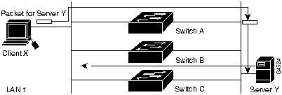
In Figure 9-2, it is possible for packets from Client X to be switched by Switch A and then for Switch B to put the same packet back on to LAN 1. In this situation, packets loop and undergo multiple replications. To prevent looping and replication, topologies that may contain loops need to run the Spanning-Tree Protocol. The Spanning-Tree Protocol uses the spanning-tree algorithm to construct topologies that do not contain any loops. Because the spanning-tree algorithm places certain connections in blocking mode, only a subset of the network topology is used for forwarding data. In contrast, routers provide freedom from loops and make use of optimal paths.
In transparent switching, neighboring switches make topology decisions locally based on the exchange of Bridge Protocol Data Units (BPDUs). This method of making topology decisions means that convergence on an alternate path can take an order of magnitude longer than in a routed environment.
In a routed environment, sophisticated routing protocols, such as Open Shortest Path First (OSPF) and Enhanced Interior Gateway Routing Protocol (Enhanced IGRP), maintain concurrent topological databases of the network and allow the network to converge quickly.
LAN switches do not filter broadcasts, multicasts, or unknown address frames. The lack of filtering can be a serious problem in modern distributed networks where broadcast messages are used to resolve addresses and dynamically discover network resources such as file servers. Broadcasts originating from each segment are received by every computer in the switched internetwork. Most devices discard broadcasts because they are irrelevant, which means that large amounts of bandwidth are wasted by the transmission of broadcasts. In some cases, the circulation of broadcasts can saturate the network so that there is no bandwidth left for application data. In this case, new network connections cannot be established, and existing connections may be dropped (a situation known as a broadcast storm). The probability of broadcast storms increases as the switched internetwork grows. (For more information about the impact of broadcasts, see Appendix E, "Broadcasts in Switched LAN Internetworks.")
Routers do not forward broadcasts, and, therefore, are not subject to broadcast storms.
Transparently switched internetworks are composed of physically separate segments, but are logically considered to be one large network (for example, one IP subnet). This behavior is inherent to the way that LAN switches work---they operate at OSI Layer 2 and have to provide connectivity to hosts as if each host were on the same cable. Layer 2 addressing assumes a flat address space with universally unique addresses.
Routers operate at OSI Layer 3, so they are able to formulate and adhere to a hierarchical addressing structure. Routed networks can associate a logical addressing structure to a physical infrastructure so that each network segment has, for example, a TCP/IP subnet or IPX network. Traffic flow on routed networks is inherently different from traffic flow on switched networks. Routed networks have more flexible traffic flow because they are able to use the hierarchy to determine optimal paths depending on dynamic factors such as network congestion.
Information is available to routers and switches that can be used to create more secure networks. LAN switches may use custom filters to provide access control based on destination address, source address, protocol type, packet length, and offset bits within the frame. Routers can filter on logical network addresses and provide control based on options available in Layer 3 protocols. For example, routers can permit or deny traffic based on specific TCP/IP socket information for a range of network addresses.
Two factors need to be considered with regard to mixed-media internetworks. First, the maximum transfer unit (MTU) differs for various network media. Table 9-1 lists the maximum frame size for various network media.
Table 9-1 MTUs for Various Network Media
| Media | Minimum valid frame | Maximum valid size |
|---|---|---|
| Ethernet | 64 bytes | 1518 bytes |
| Token Ring | 32 bytes | 16 KB theoretical,4 K normal |
| FDDI | 32 bytes | 4400 bytes |
| ATM LANE | 64 bytes | 1518 bytes |
| ATM Classical IP | 64 bytes | 9180 bytes |
| Serial HDLC | 14 bytes | No limit,4.5 KB normal |
When LANs of dissimilar media are switched, hosts must use the MTU that is the lowest common denominator of all the switched LANs that make up the internetwork. This requirement limits throughput and can seriously compromise performance over a relatively fast link such as FDDI or ATM. Most Layer 3 protocols can fragment and reassemble packets that are too large for a particular subnetwork, so routed networks can accommodate different MTUs, which maximizes throughput.
Second, because they operate at Layer 2, switches must use a translation function to switch between dissimilar media. The translation function can result in serious problems such as non-canonical versus canonical Token Ring-to-Ethernet MAC format conversion.
By working at Layer 3, routers are essentially independent of the properties of any physical media and can use a simple address resolution algorithm (such as Novell-node-address = MAC-address) or a protocol such as the Address Resolution Protocol (ARP) to resolve differences between Layer 2 and Layer 3 addresses.
An individual switch might offer some or all of the following benefits:
Because routers use Layer 3 addresses, which typically have structure, routers can use techniques (such as address summarization) to build networks that maintain performance and responsiveness as they grow in size. By imposing structure (usually hierarchical) on a network, routers can effectively use redundant paths and determine optimal routes even in a dynamically changing network. This section describes the router functions that are vital in switched LAN designs:
Routers control broadcasts and multicasts in the following ways:
Successful network designs contain a mix of appropriately scaled switching and routing. Given the effects of broadcast radiation on CPU performance, well-managed switched LAN designs must include routers for broadcast and multicast management. Table 9-2 provides a rough guide for the maximum number of hosts that can reside in a flat network.
Table 9-2 Scalability Guidelines for Flat Networks
| Protocol | Number of Hosts |
|---|---|
| IP | 500 |
| IPX | 300 |
| AppleTalk | 200 |
| Multiple protocols | 200 |
In addition to preventing broadcasts from radiating throughout the network, routers are also responsible for generating services to each LAN segment. The following are examples of services that the router provides to the network for a variety of protocols:
In a flat virtual network, a single router would be bombarded by a myriad of requests needing replies, severely taxing its processor. Therefore, the network designer needs to consider the number of routers that can provide reliable services to a given subset of virtual LANs. Some type of hierarchical design needs to be considered.
In the past, routers have been used to connect networks of different media types, taking care of the OSI Layer 3 address translations and fragmentation requirements. Routers continue to perform this function in switched LAN designs. Most switching is done within like media (such as Ethernet, Token Ring, and FDDI switches), with some capability of connecting to another media type. However, if a requirement for a switched campus network design is to provide high-speed connectivity between unlike media, routers play a significant part in the design.
A virtual LAN (VLAN) consists of a number of end systems, either hosts or network equipment (such as bridges and routers), connected by a single bridging domain. This bridging domain is supported on various pieces of network equipment (for example, LAN switches) that operate bridging protocols between them, with a separate bridge group for each VLAN.
First-generation VLANs are based on various OSI Layer 2 bridging and multiplexing mechanisms, such as IEEE 802.10, LAN Emulation (LANE), and Inter-Switch Link (ISL), that allow the formation of multiple, disjointed, overlaid broadcast groups on a single network infrastructure. Figure 9-3 shows an example of a switched LAN network that uses VLANs.
Figure 9-3 Typical VLAN Topology
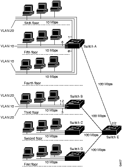
In Figure 9-3, 10-Mbps Ethernet connects the hosts on each floor to switches A, B, C, and D. 100-Mbps Fast Ethernet connects these to Switch E. VLAN 10 consists of those hosts on ports 6 and 8 of Switch A and Port 2 on Switch B. VLAN 20 consists of those hosts that are on Port 1 of Switch A and Ports 1 and 3 of Switch B.
VLANs can be used to group a set of related users, regardless of their physical connectivity. They can be located across a campus environment or even across geographically dispersed locations. The users might be assigned to a VLAN because they belong to the same department or functional team, or because data flow patterns among them is such that it makes sense to group them together. Note, however, that without a router, hosts in one VLAN cannot communicate with hosts in another VLAN.
Virtual LANs solve some of the scalability problems of large flat networks by breaking a single bridged domain into several smaller bridged domains, each of which is a virtual LAN. Note that each virtual LAN is itself constrained by the scalability issues described in Appendix E, "Broadcasts in Switched LAN Internetworks." It is insufficient to solve the broadcast problems inherent to a flat switched network by superimposing virtual LANs and reducing broadcast domains. VLANs without routers do not scale to large campus environments. Routing is instrumental in the building of scalable VLANs and is the only way to impose hierarchy on the switched VLAN internetwork.
This section examines virtual LANs and presents general network designs that successfully implement switched LANs and VLANs. The terms switching and bridging are used interchangeably.
The section discusses the following topics:
VLANs offer the following features:
This section describes the different methods of creating the logical groupings (or broadcast domains) that make up various types of VLANs. There are three ways of defining a VLAN:
Cisco's initial method of implementing VLANs on routers and Catalyst switches is by port. To operate and manage efficiently protocols such as IP, IPX, and AppleTalk, all nodes in a VLAN should be in the same subnet.
Cisco uses three different technologies to implement VLANs:
The three technologies are similar in that they are based on OSI Layer 2 bridge multiplexing mechanisms.
IEEE 802.10 defines a method for secure bridging of data across a shared metropolitan area network (MAN) backbone. Cisco has initially implemented the relevant portions of the standard to allow the "coloring" of bridged traffic across high-speed backbones (FDDI, Fast Ethernet, Ethernet, Token Ring, and serial links).
There are two strategies using IEEE 802.10 to implement VLANs, depending on how traffic is handled through the backbone:
In the bridged backbone topology shown in Figure 9-4, you want to ensure that bridged traffic only goes between Segment A and Segment D (both in VLAN 10) and Segment B and Segment C (both in VLAN 20).
Figure 9-4 IEEE 802.10 Bridged Backbone Implementation

In Figure 9-4, all Ethernet ports on Bridges X, Y, and Z are in a VLAN and are to be VLAN interfaces. All FDDI interfaces in bridges X, Y, and Z are called transit bridge interfaces. To ensure that traffic from Segment A destined for Segment D on Bridge Z is forwarded onto Ethernet 3 and not onto Ethernet 2, it is colored when it leaves Bridge X. Bridge Z recognizes the color and knows that it must forward these frames onto Ethernet 3 and not onto Ethernet 2.
The coloring of traffic across the FDDI backbone is achieved by inserting a 16-byte header between the source address and the Link Service Access Point (LSAP) of frames leaving a bridge. This header contains a 4-byte VLAN ID or "color." The receiving bridge removes the header and forwards the frame to interfaces that match that VLAN color.
In the routed backbone topology shown in Figure 9-5, the goal is the same as for the bridged topology---that is, to ensure that bridged traffic only goes between Segment A and Segment D (both in VLAN 10) and Segment B and Segment C (both in VLAN 20).
Figure 9-5 IEEE 802.10 Routed Backbone Implementation

As stated earlier in this chapter, it is important that a single VLAN use only one subnet. In Figure 9-5, VLAN 10 (subnet 10) is "split" and therefore must be "glued" together by maintaining a bridged path for it through the network. For Switch X and nodes in VLAN 20 (subnet 20), traffic is switched locally if appropriate. If traffic is destined for a node in VLAN 30 (subnet 30) from a node in VLAN 20, Router Y routes it through the backbone to Router Z. If traffic from Segment D on VLAN 10 is destined for a node in VLAN 20, Router Y routes it back out the FDDI interface.
The difference between these two strategies is subtle. Table 9-3 compares the advantages and disadvantages of the two strategies.
Table 9-3 Advantages and Disadvantages of Bridged and Routed Backbones
| Bridged Backbone | Routed Backbone | ||
|---|---|---|---|
| Advantages | Disadvantages | Advantages | Disadvantages |
| Propagates color information across entire network. | Backbone is running bridging. | No bridging in backbone. | Color information is not propagated across backbone and must be configured manually. |
| Allows greater scalability by extending bridge domains. | Easy to integrate into existing internetwork. | If subnets are split, a bridged path has to be set up between switches. | |
| Can run native protocols in the backbone. | |||
A VLAN interface can have only one VLAN ID, and transit bridge interfaces initially support up to 64 VLANs across them. Configuration of VLANs is achieved using the normal set of transparent bridging commands, using separate bridge groups for VLANs and using subinterfaces on transit interfaces. The only extra bridging configuration parameter is for configuration of VLAN IDs.
Inter-Switch Link (ISL) is a Cisco-proprietary protocol for interconnecting multiple switches and maintaining VLAN information as traffic goes between switches. This technology is similar to IEEE 802.10 in that it is a method of multiplexing bridge groups over a high-speed backbone. It is only defined on Ethernet and Fast Ethernet. The discussion of routing and bridging in the backbone in the section "IEEE 802.10," earlier in this chapter also applies to ISL.
With ISL, an Ethernet frame is encapsulated with a header that maintains VLAN IDs between switches. A 30-byte header is prepended to the Ethernet frame, and it contains a 2-byte VLAN ID.
Figure 9-6 Inter-Switch Link Design
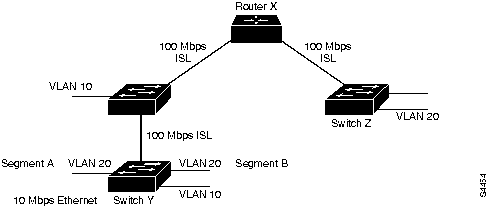
In Figure 9-6, Switch Y switches VLAN 20 traffic between segments A and B if appropriate. Otherwise, it encapsulates traffic with an ISL header that identifies it as traffic for VLAN 20 and sends it through the interim switch to Router X.
Router X routes the packet to the appropriate interface, which could be through a routed network beyond Router X (as in this case) out the Fast Ethernet interface to Switch Z. Switch Z receives the packet, examines the ISL header noting that this packet is destined for VLAN 20, and switches it to all ports in VLAN 20 (if the packet is a broadcast or multicast) or the appropriate port (if the packet is a unicast).
LAN Emulation (LANE) is a service that provides interoperability between ATM-based workstations and devices connected to existing legacy LAN technology. The ATM Forum has defined a standard for LANE that provides to workstations attached via ATM the same capabilities that they are used to obtaining from legacy LANs.
LANE uses MAC encapsulation (OSI Layer 2) because this approach supports the largest number of existing OSI Layer 3 protocols. The end result is that all devices attached to an emulated LAN appear to be on one bridged segment. In this way, AppleTalk, IPX, and other protocols should have similar performance characteristics as in a traditional bridged environment. In ATM LANE environments, the ATM switch handles traffic that belongs to the same emulated LAN (ELAN), and routers handle inter-ELAN traffic.
For more information about LANE, see Chapter 5, "Designing ATM Internetworks."
In traditional networks, there are usually several well-known servers, such as e-mail and corporate servers, that almost everyone in an enterprise needs to access. If these servers are located in only one VLAN, the benefits of VLANs will be lost because all of the different workgroups will be forced to route to access this common information source.
This problem can be solved with LANE and virtual multihomed servers, as shown in Figure 9-7. NICs such as the Zeitnet allow workstations and servers to join up to eight different VLANs. This means that the server will appear in eight different ELANs and that to other members of each ELAN, the server appears to be like any other member. This capability greatly increases the performance of the network as a whole because common information is available directly through the optimal Data Direct VCC and does not need to be routed.
Figure 9-7 Multihomed Servers in an ATM Network

To multihome servers in non-ATM environments, there are two possible choices:
When designing switched LAN networks, you should take into account the following considerations:
Good network design is based on many concepts that are summarized by the following key principals:
Figure 9-8 shows a high-level view of the various aspects of a hierarchical network design. A hierarchical network design presents three layers---core, distribution, and access---with each layer providing different functionality.
Figure 9-8 Hierarchical Network Design Model

The core layer is a high-speed switching backbone and should be designed to switch packets as fast as possible. This layer of the network should not perform any packet manipulation access lists and filtering that would slow down the switching of packets.
The distribution layer of the network is the demarcation point between the access and core layers and helps to define and differentiate the core. The purpose of this layer is to provide boundary definition and is the place at which packet manipulation can take place. In the campus environment, the distribution layer can include several functions, such as the following:
In the non-campus environment, the distribution layer can be a redistribution point between routing domains or the demarcation between static and dynamic routing protocols. It can also be the point at which remote sites access the corporate network. The distribution layer can be summarized as the layer that provides policy-based connectivity.
The access layer is the point at which local end users are allowed into the network. This layer may also use access lists or filters to further optimize the needs of a particular set of users. In the campus environment, access-layer functions can include the following:
In the noncampus environment, the access layer can give remote sites access to the corporate network via some wide-area technology, such as Frame Relay, ISDN, or leased lines.
It is sometimes mistakenly thought that the three layers (core, distribution, and access) must exist in clear and distinct physical entities, but this does not have to be the case. The layers are defined to aid successful network design and to represent functionality that must exist in a network. The instantiation of each layer can be in distinct routers or switches, can be represented by a physical media, can be combined in a single device, or can be omitted altogether. The way the layers are implemented depends on the needs of the network being designed. Note, however, that for a network to function optimally, hierarchy must be maintained.
With respect to the hierarchical model, traditional campus LANs have followed one of two designs: single router or distributed backbone.
Figure 9-9 Traditional Campus Design

In the single-router design, the core and distribution layers are present in a single entity---the router. Core functionality is represented by the backplane of the router and distribution is represented by the router. Access for end users is through individual- or chassis-based hubs. This design suffers from scalability constraints because the router can be only be in one physical location, so all segments end at the same location---the router. The single router is responsible for all distribution functionality, which can cause CPU overload.
The distributed backbone design uses a high-speed backbone media, typically FDDI, to spread routing functionality among several routers. This also allows the backbone to traverse floors, a building, or a campus.
When designing switched LAN campus networks, the following factors must be considered:
Campus network designs are evolving rapidly, with the deployment of switching at all levels of the network---from the desktop to the backbone. Three topologies have emerged as generic network designs:
The scaled switching design shown in Figure 9-10 deploys switching at all levels of the network without the use of routers. In this design, each layer consists of switches, with switches in the access layer providing 10-Mbps Ethernet or 16-Mbps Token Ring to end users.
Figure 9-10 Scaled Switching Design
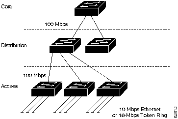
Scaled switching is a low cost and easy-to-install solution for a small campus network. It does not require knowledge of address structure, is easy to manage, and allows all users to communicate with each other. However, this network comprises a single broadcast domain, so it must operate within the scalability rules defined in Table 9-2. If a scaled switched network needs to grow beyond the rules defined in Table 9-2, it can use VLANs to create multiple broadcast domains. Note that when VLANs are used, end users in one VLAN cannot communicate with end users in another VLAN unless routers are deployed.
The route server/centralized routing design deploys switching at the access layer of the network and either ATM switching or LAN switching at the distribution layer of the network, as shown in Figure 9-11.
Figure 9-11 Route Server/Centralized Routing Design

In the route server/centralized routing design, the core layer consists of routers, and the distribution layer can consist of ATM switches, Fast Ethernet LAN switches, or FDDI LAN switches. The access layer consists of LAN switches providing 10-Mbps Ethernet or 16-Mbps Token Ring to end users.
In the case of ATM in the distribution layer, the following key issues are relevant:
In the case of LAN switching in the distribution layer, the following key issues are relevant:
To scale the route server/centralized routing design, a logical hierarchy must be imposed. The logical hierarchy consists of VLANs and routers that enable inter-VLAN communication. In this topology, routing is used only in the core layer, and the access layer depends on bandwidth through the distribution layer to gain access to routing functionality in the core layer.
The route server/centralized routing design scales well when VLANs are designed so that the majority of resources are available in the VLAN. Therefore, if this topology can be designed so that 80 percent of traffic is intra-VLAN and only 20 percent of traffic is inter-VLAN, the bandwidth available for access to routing in the core is not a concern. However, if inter-VLAN traffic is greater than 20 percent, access to routing in the core becomes a scalability issue. For optimal network operation, scalable routing functionality is needed at the distribution layer of the network.
The distributed routing design deploys switching in the access layer, routing in the distribution layer, and some form of high-speed switching in the core layer, as shown in Figure 9-12.
Figure 9-12 Distributed Routing Design
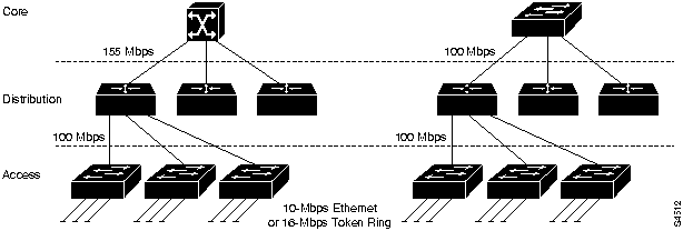
The distributed routing design follows the classic hierarchical network model both physically and logically. Because it provides high bandwidth for access to routing functionality, this design scales very well. The scalability rules listed in Table 9-2 also apply to this topology.
Campus LAN designs use switches to replace traditional hubs and use an appropriate mix of routers to minimize broadcast radiation. With the appropriate pieces of software and hardware in place, and adhering to good network design, it is possible to build topologies such as the examples described in the section "Switched LAN Network Designs" earlier in this chapter.
Copyright 1988-1996 © Cisco Systems Inc.